Author Topic: Volume difference between units

April 21, 2021, 11:20:54 AM
Read 3198 times

Dolbah

  • Jr. Member
  • **
  • Posts: 60
  • Karma: +0/-0
    • View Profile
Greetings

I've buildt 2 units.
FYI: Both are missing U1 and i have temporarily shorted the center and right hole as instructed (Are the replacements on the way??)

There is a volume difference between the units at 9,2 dB. This is both via XLR and the DI.
Cables and slots have been switched for cross-reference.

  • Setup went flawlessly on both units
  • JMP3 jumper is removed on both
  • Volume has been checked with same settings on both units
  • CN1 jumper i sitiated at center and right pin on CN1, both units

I have attacked this as if the one with the lowest volume has an error, so i did a Reflow of all joints on the input transformer and did a second visual and clean of the board. I have also switched output transformers, and the issue does not follow the transformer

Went over to the the pinned post, and checked values:

Low Unit (VDC):
 
A:  2,6
B: 4,1
C: 22,6
D: 13,6
E: 2,1
F: 12,9
G: 1,0
H: 4,0
I: 0,4
J: 3,5
K: 22,9
L: 2,9


Following the signal (2.0 VAC):

• Input transformer pin 7 = No measurement
• TP1 = 0,3 VAC
• output transformer yellow wire: 49,7 VAC


High unit (VDC):

A: 2,6
B: 4,1
C: 22,5
D: 13,5
E: 2,1
F: 12,9
G: 1,0
H: 4,1
I: 0,4
J: 3,5
K: 22,7
L: 3,0

Following the signal (2.0 VAC):

• Input transformer pin 7 = 0 measurement
• TP1 = 1,3 VAC
• output transformer yellow wire: 49,3 VAC


So i have issues follwing the signal as described, but this is almost the same on both units, and the high unit sound and feel pretty perfect, so cant see any issues with it.
TP1 meassures 1VAC differently on the high vs low board.   Is this the problem area?


April 21, 2021, 02:28:43 PM
Reply #1

Dolbah

  • Jr. Member
  • **
  • Posts: 60
  • Karma: +0/-0
    • View Profile
Also.. just FYI. The 6 step switch for SW4 in the packages i received had no small holes like these.


Most likely nothing to do with the gain difference, but just in case they are the wrong parts

April 21, 2021, 02:56:05 PM
Reply #2

Dolbah

  • Jr. Member
  • **
  • Posts: 60
  • Karma: +0/-0
    • View Profile
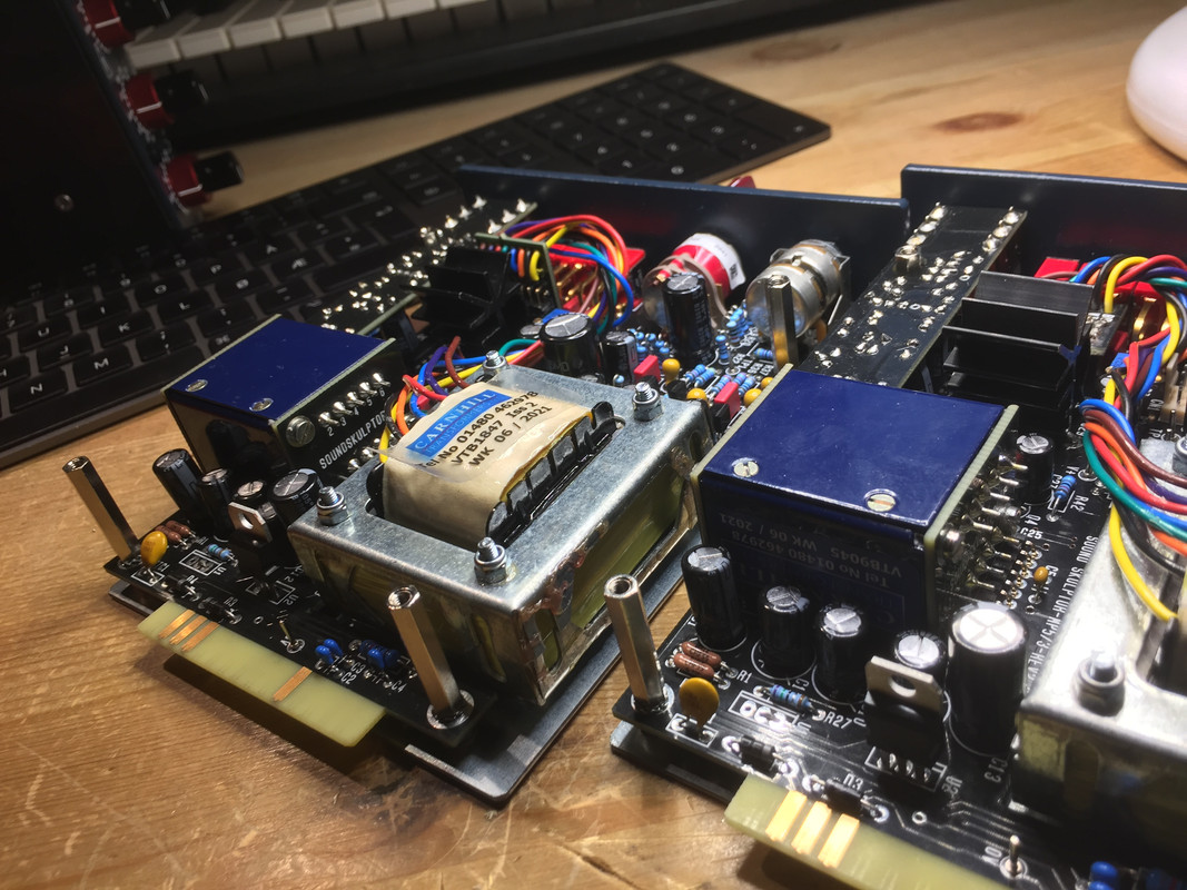
So got around to test the input transformers:

Low volume unit:

CARNHILL VTB1847 (unplugged) :
• Yellow-Orange : 8,2 ohms
• Red-Brown : 6.9 ohms
• Blue-Green : 21,9 ohms
• Violet-Black : 21,8 ohms

CARNHILL VTB9045 :
• 2-4 : 149 ohms
• 3-5 : 149,3 ohms
• 7-9 : 25 ohms
• 8-10 : 24,8  ohms


High Volume unit:


CARNHILL VTB1847 (unplugged) :
• Yellow-Orange : 8,2 ohms
• Red-Brown : 6.9 ohms
• Blue-Green : 21,9 ohms
• Violet-Black : 21,9 ohms

CARNHILL VTB9045 :
• 2-4 : 25,5 ohms
• 3-5 : 25,5 ohms
• 7-9 : 135,8 ohms
• 8-10 : 135,4  ohms

So yeah, as suspected.. the low volume unit measures differently on the input transformer. Actually it measures kind of opposite.

My first thought was that i had installed it upside down, but the pins are A-symetrtical so that is not possible.

What i do see though, is that the Carnhill logo is also reversed on the transformer. Could it really have been assembled wrong at the factory?
The one to the right is the one measureing wrong:


« Last Edit: April 21, 2021, 02:59:20 PM by Dolbah »

April 21, 2021, 03:47:05 PM
Reply #3

Dolbah

  • Jr. Member
  • **
  • Posts: 60
  • Karma: +0/-0
    • View Profile

My first thought was that i had installed it upside down, but the pins are A-symetrtical so that is not possible.


What a liar i am!

I desoldered the transformer, and it was indeed the wrong way.

Switching it around now

April 21, 2021, 04:02:28 PM
Reply #4

Dolbah

  • Jr. Member
  • **
  • Posts: 60
  • Karma: +0/-0
    • View Profile
All good now!   Rookie misstake :o

I'll leave this thread here as fear and warning to others  8)

April 21, 2021, 04:13:08 PM
Reply #5

JPK

  • Administrator
  • Hero Member
  • *****
  • Posts: 1012
  • Karma: +30/-0
    • View Profile
Great job of solving the issue by yourself!
JPK

April 21, 2021, 04:20:33 PM
Reply #6

Dolbah

  • Jr. Member
  • **
  • Posts: 60
  • Karma: +0/-0
    • View Profile
Great job of solving the issue by yourself!
Thank you!

What are the stat on replacements for the wrong U1 parts?

April 21, 2021, 06:52:58 PM
Reply #7

JPK

  • Administrator
  • Hero Member
  • *****
  • Posts: 1012
  • Karma: +30/-0
    • View Profile
The U1 IC's were mailed on Monday.
JPK

May 08, 2021, 08:24:26 PM
Reply #8

Dolbah

  • Jr. Member
  • **
  • Posts: 60
  • Karma: +0/-0
    • View Profile
The U1 IC's were mailed on Monday.
Hi
I still havent received these, and U1 i still shorted. Can this have any sideeffects over time?   Suddenly on of my units started behaving differently, the XLR input is much higher then it should. The DI is still on normal volume.

May 10, 2021, 05:44:20 PM
Reply #9

JPK

  • Administrator
  • Hero Member
  • *****
  • Posts: 1012
  • Karma: +30/-0
    • View Profile

Quote
Can this have any sideeffects over time?
Absolutely not. This IC only limits the inrush current at power up and has no effect after.


Quote
the XLR input is much higher then it should. The DI is still on normal volume.
The DI goes through the same path as the XLR. I would suspect a connection issue.

JPK

May 12, 2021, 01:46:57 AM
Reply #10

jrasia

  • Newbie
  • *
  • Posts: 1
  • Karma: +0/-0
    • View Profile

My first thought was that i had installed it upside down, but the pins are A-symetrtical so that is not possible.


What a liar i am!

I desoldered the transformer, and it was indeed the wrong way.

Switching it around now
How were you able to desolder the input transformer exactly?  So many solder points on the PCB not to mention the relays are tight to the header pads.  Just realized I did the exact same thing as you but 7 out 8 modules are reversed!! Grrrrr....

May 12, 2021, 09:02:26 AM
Reply #11

JPK

  • Administrator
  • Hero Member
  • *****
  • Posts: 1012
  • Karma: +30/-0
    • View Profile
In case you need to remove the input transformer follow these steps
Remove the 4 screws on the Carnhill transformer (2 in front and 2 in the back).
Remove solder on the 7 pads of the back daughter board and remove it. Use a desoldering pump.
Remove solder on the 9 pads connecting the transformer in/outs on the front daughter board and remove the transformer. Be careful when removing the front daughter board not to pull the transformer front plate with it because it is not attached anymore
JPK