Show Posts

This section allows you to view all posts made by this member. Note that you can only see posts made in areas you currently have access to.

Messages - musicarr

Pages: [1]
1
Got it. I know what to get for the C20, then. Thanks.

2
Another question: what tolerance is recommended for the capacitors? 1%, 5%, 10%, or is 20% fine, too? Do tolerances differ for different kinds of capacitors used in these audio units, or is it the same pretty much across the board? Thanks.

3
Great! Thanks for the info. I know what to look for now.

4
Thanks for the confirmation. Are there brands that you are familiar with that you recommend?

5
Go it. Thanks for the clarification. Just to see if that might be the case, I'll replace it. As a reference, it was C20 that I had backwards. Just to be sure I'm ordering the correct replacement, I'm looking for a 22uf 16v tantalum capacitor to replace C20. Is this what I'm looking for (amazon)?

https://www.amazon.com/Uxcell-a14042900ux0341-Yellow-Tantalum-Capacitors/dp/B00PZLX93O/

Thanks

6
I checked all the electrolytic and tantalum caps. There was one tantalum cap that was backwards. I switched it to the correct polarity and the "bib pop" is gone. So that must have been the issue. There still is a slight "pop" going from 20 dB to 30 dB. It registers at about -30 db on the Pro Tools meter. The other positions don't seem to have that large a "pop", as they register about -45 dB on the Pro Tools meter. Is there something else I should look at, or is that "pop" going from 20 dB to 30 dB "normal"?

7
With the electrolytic caps, it's easier to see where the negative and positive wires are. And on the tantalum caps, the "+" sign to the right of the labeling points to the positive lead. Is it possible, sometimes, that the "longer" lead of might not be the positive lead? I was going off of the longest lead on the tantalum caps. Is that reliable, or should you always look for the "+" marking to know which lead is the positive?

8
I was consciously, and verbally, careful to the direction of all caps set correctly. But it doesn't mean I missed one somewhere. I'll check every cap and let you know what I find. 

9
MP573 Microphone preamplifier / Loud Pop When Changing dB Rotary Switch
« on: August 25, 2025, 03:11:47 AM »
Hi,

I've just finished building my second MP573. Both of them seem to be working well, from the tests I've done according to the Setup Guide. All tests were good. But on the first one, when changing the dB level on the rotary switch, there are little pops, not terrible, but present. On the second one, the pops are quite pronounced, especially when going from 20 to 30 dB. So much so that it puts the meters into the red within Pro Tools.

So main question: Is this normal, or should there be no pop at all when change dB positions on the rotary switch?

I searched for "pop" in the support forums and found the following two threads:


As I'm quite new to DIY, I didn't fully understand all that was said in the above threads, hence this new thread. Sounds like the pops should not be happing. What would be my starting point to test for what might be wrong?

Thanks

10
MP573 Microphone preamplifier / Re: R47 and R20 Differences
« on: August 05, 2025, 12:44:38 AM »
Got it. Thanks for the confirmation and clarification.

11
MP573 Microphone preamplifier / R47 and R20 Differences
« on: August 03, 2025, 04:09:31 PM »
Hi,

Finished my first unit build, and it worked great. Love the sound. I've started working on the 2nd one. I've just run into a little confusion that I don't remember having on the first unit. I'm thinking I just got lucky, with the first unit, as I seems to be working great.

I noticed that R47 and R20 have the same color rings and order: yellow, violet, black, gold, brown. But the R47 is 1/2 watt, where as R20 is 1/4 watt. The R47 is horizontal on the board, and the R20 is vertical. The R47 is a larger resistor, whereas the R20 is smaller like the majority of the other resistors. On the PCB, R47 has a larger "outline" than the other resistors, minus R26, which is also larger and 1/2 watt. Seems like the R47 is indeed 1/2 watt, and not 1/4 watt, simply because of it's physical size, and the "hint" of a larger outline on the PCB. Pretty sure that is correct. Is it?

Secondarily, as very much a beginner, it's not perfectly clear to me that the larger resistor is the 1/2 watt and the smaller resistor is the 1/4 watt, as they both have the same colored rings and order. Is that normal that two resistors would have the same colored rings and order, but different wattages? If so, how would I tell the difference between the two, visually, other than with a multimeter?

Thanks
12
MP573 Microphone preamplifier / Re: Short Circuit Test
« on: July 07, 2025, 06:26:21 PM »
Got it. Thanks.

13
MP573 Microphone preamplifier / Re: Short Circuit Test
« on: July 07, 2025, 02:43:00 PM »
Great, sounds like I'm ready to continue testing.

As to the readings I WAS getting - is that what I should see? What do they tell me? Just trying to understand everything.

Thanks

14
MP573 Microphone preamplifier / Short Circuit Test
« on: July 07, 2025, 03:10:31 AM »
Hi,

I've finished doing the build, and have started testing. Step #1 is to do a short circuit test. As I am very new to this, I'm uncertain as to how to specifically go about getting the correct readings. Here's what I've done so far and the readings I've gotten.


Multimeter set at 200k ohms
Black test lead is on common input
Red test lead is on ohms input

Check #1
-------------------------
V- has black test lead
OV has red test lead
Result: 80.xx - continues to slowly increment

Check #2
-------------------------
V+ has red test lead
OV has black lead
Result: 75.xx - continues to slowly increment

Any other combination of leads on V-, OV, and V+, gives me a reading of ‘OL’ which according to my multimeter, is ‘over limit’, but that’s also what it says when the leads aren’t touching anything.

What I don’t know is if these readings are what they should be. I’m very knew to this, so any input is helpful, as I continue to learn.


One thing I was also a little confused about the JMP3. Should it have the jumper in place or not when doing the Short Circuit test? The build guide directs say to put it on, so by the time you get to the setup guide, I'm assuming it's supposed to still be on, as I didn't see anywhere saying to take it off. But -- in step #2 of the setup guid, it says to the put the jumper on, which is odd, as it's already on. Did I miss something saying to take it off before doing test #1, or should is still be on?

Thanks

15
MP573 Microphone preamplifier / Re: Missing Capacitors
« on: June 26, 2025, 09:43:56 PM »
Hi -- Just letting you know I've received the caps. Thanks very much.

16
MP573 Microphone preamplifier / Re: C34 Film Capacitor Placement
« on: June 23, 2025, 11:50:32 PM »
Perfect. Thanks for the info and confirmation.

17
MP573 Microphone preamplifier / C34 Film Capacitor Placement
« on: June 22, 2025, 11:53:15 PM »
Hi,

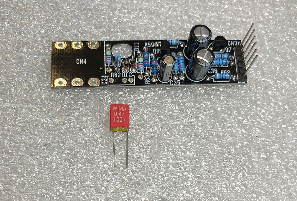
The C34 Film Capacitor has two pins, but the PCB has three holes. Which holes should the capacitor go in?

Also, just want to confirm that the "WIMA 0,47 100-" is indeed the C34 capacitor. Is that correct?

Thanks.


18
MP573 Microphone preamplifier / Re: Missing Capacitors
« on: June 03, 2025, 02:19:21 PM »
Sounds good. I purchased two pre's so I'll use the ones from the 2nd pre to finish the first one. By the time the caps get here from you, I'll be ready to build the 2nd one. All good. Thanks.

19
MP573 Microphone preamplifier / Missing Capacitors
« on: June 02, 2025, 04:48:15 PM »
Hi,

I'm in the middle of the build, and it looks like I'm short three (3) 330u-25v capacitors. There should have been 9, but there were only 6. I purchased two of the pre's and checked the second one, and there are 9 there, so that's good. But I'm short three (3) on the one I'm currently building. What's my best option here? Do you send me the 3 missing capacitors, or shall I just get them another source like amazon:

Replacement for 6 pcs Panasonic FM Series Capacitors 25V 330uf Low Impedance
https://www.amazon.com/pcs-Panasonic-FM-Capacitors-330uf/dp/B073YR6GCY/ref=sr_1_1_sspa?crid=2FZSVGKV9AHY6&dib=eyJ2IjoiMSJ9.lYGszSaGmIKqSmxQ-NYYR3toB8oaNxkK1x6ow_9wMxRNUkzN02RcFEcB3edtqYU9UtljTMxS0N6U717AmUy53o8btpqtdoBJVeTYAm_l0R3h-6-EotxYrAY9uudKCvvi8K02SvPwAy9CEQ-2dn7UUFWkgOnpxVdACeHKNRSpjB0XZWaVvJdwpTo5GnCYXifRGbXCMuf5gjOP7P07xCfgDqmMKBiYHhYITMEqpUO3dig.ODc-pEs8bNJvWepUptD3d3cL4qy-FmY6WLl7NM9Gcik&dib_tag=se&keywords=330uf+25v+capacitor&qid=1748875453&sprefix=capacitor+330uf%2Caps%2C181&sr=8-1-spons&sp_csd=d2lkZ2V0TmFtZT1zcF9hdGY&psc=1

If the latter, I just want to make sure I get the correct ones.

Thanks

20
Thanks very much for the confirmation. I'll get started building.

21
In looking at the DOCS on the product page a little closer, it says, "from DOCS-20". The previous versions of DOCS suggest ranges, i.e. "from DOCS-13 to DOCS-19". Is it safe to assume that "from DOCS-20" is the correct assembly instructions from DOCS-20 through all others after that ?

22
Hi,

Was about ready to start my build. On the outside of the box, is says, "DOCS-24". I'm presuming that's the current exact docs version I need for this version of the kit I have. But on the product page, it only goes up to "DOCS-20". Where can I find "DOCS-24"?

Thanks.

23
XT500 Lunchbox connector extender / Re: Ribbon Cable Direction
« on: April 28, 2025, 02:23:46 PM »
Cool. That works for me. Just wanted to be sure what I did was correct. Thanks for the confirmation.

24
XT500 Lunchbox connector extender / Ribbon Cable Direction
« on: April 27, 2025, 11:10:47 PM »
Hi,

Getting ready to build my first Sound Skulptor units (MP573). In prep for that, I'm building the XT500. It looks like the ribbon cable has one "wire" at the top that is red. On the each of the two PCB's, there is a white dot. From what I can glean from the two images on the product page, the top, red "wire" on the cable should be oriented to the white dot's on the two PCB's. Is that correct? If so, and because the ribbon cable connectors can only go fit in one direction in the ribbon connector sockets, it looks like the cable that connects to the PCB that connects to the inside of the 500 series chassis is 180 degrees different than what's in the product images. See images. It'll be a little cumbersome to get it into the 500 chassis because of the cable direction/orientation of the ribbon connector, but if the "red line to white dot" orientation is the important part, then I guess that's the way it is. Granted, I can flip the ribbon cable, but then the ribbon will be kind of going over the test pins. Or... is the cable that was sent, manufactured 180 degrees the wrong way on one end? Just want to be sure before I use it for testing.


Thanks

Pages: [1]
SMF spam blocked by CleanTalk