26
MP573 Microphone preamplifier / Re: Volume difference between units
« on: April 21, 2021, 04:20:33 PM »Great job of solving the issue by yourself!Thank you!
What are the stat on replacements for the wrong U1 parts?
This section allows you to view all posts made by this member. Note that you can only see posts made in areas you currently have access to.
Great job of solving the issue by yourself!Thank you!


What a liar i am!
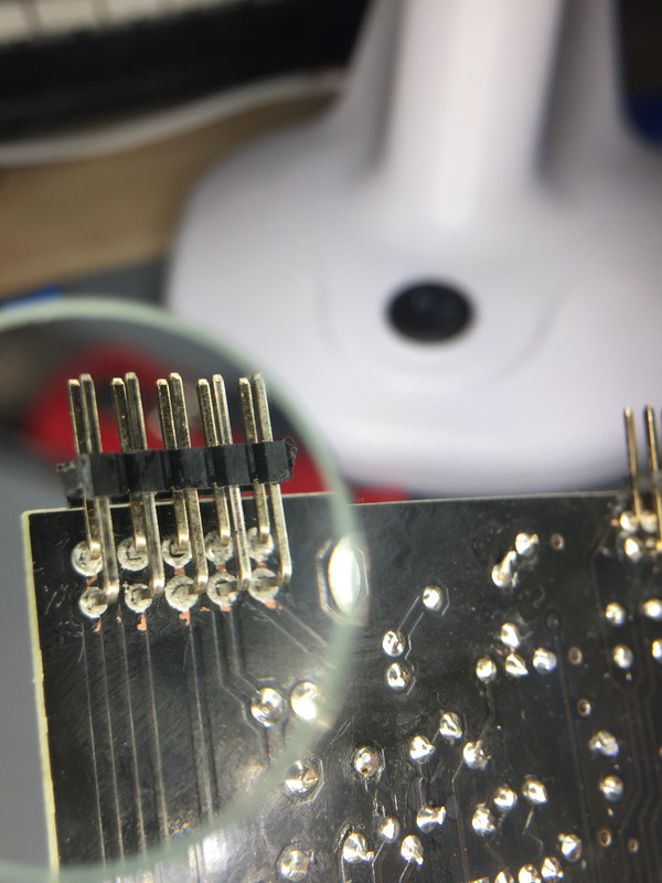
My first thought was that i had installed it upside down, but the pins are A-symetrtical so that is not possible.


There is absolutely no need of a knife to split the PCB's.
You have probably cut a track between P2 and J7a.
 i've been afraid to break the PCBs earlier, so i've used a knife to make them separate easier.
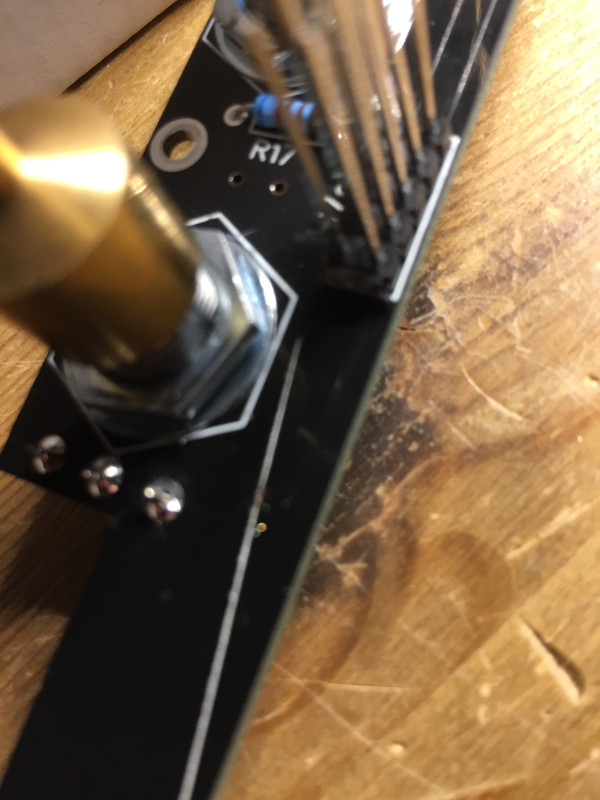
ok, i'll just have to keep myn eyes open.QuoteCould it be that the temporary insert of 1K5 did something like thisNo way.
I still believe you have had an intermittent short circuit somewhere.
And it could come back.
 Thank you.
QuoteWhat if i remove the resistor, and try to insert a new (temporary) LED againAny LED will do, the specs are very tolerant.
You got 2 LEDs burning in a row, this shows another issue.
This looks plain normal!Hmm..
Nothing happens if you shake the wires to the meter a little?
I just cannot understand how the green LED may have burnt. And why the needle went to 20.
I suspected an intermittent short circuit inside the meter.
What DC voltage across the 1k5? 8,6 VDC
What DC voltage across the 1k5?
What DC voltage across the meter small terminals?
What DC voltage across the relay (taken across D19)?
What DC voltage across R104?
Does the meter lights up?
I put R72 (1K5) in the LED spot, and yes the Relay clicks whn turning the unit on.No, i do not have any spare Resistors around. i would have to de-solder one from PCBb in that case
Can you temporarily replace the LED by a resistor of 1 to 1.5 k ?
And check if you can hear the relay clicking when you activate the compressor.
Edit: But, why not. I'll just borrow one from PCBb. I'll take R72
No, i do not have any spare Resistors around. i would have to de-solder one from PCBb in that case
Can you temporarily replace the LED by a resistor of 1 to 1.5 k ?
And check if you can hear the relay clicking when you activate the compressor.
So, i am looking at these. As next suspects.
If PCBa is disconnected i do not get a measurment.
If PCBa is connected tom PCBc, i measure 0,54 (20k on DDM) with the second down right pin. Se picture below.
Edit: I get no measurment between the corresponding pins on CN2b

I have checked this, there are no shorts between any of the meter wires.Quote569 Ohm, on large terminals and only "1" (infinite, right?) between the small onesYou must also check between the small and large terminals, in case there is a short circuit inside the meter.

